
UML stands for Unified Modelling Language. It is rich set of diagrams depicting software solution, application structure, system behavior and business processes used to transform the complex software requirements into simple visual representation to ease the understanding of such requirements.
It is important step of SDLC. It comes under Analysis and system modeling step of requirement management.
They are basically divided into two types:
- Structure diagrams
- Behavior diagrams
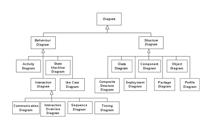
Structure diagrams includes:
- Class diagram: Basic block of any object oriented programming language based solution. It represents object having similar responsibilities. It has three parts: name of class, set of attributes and method or functions. Figure below shows a sample class.

- Object diagram: They are instance of a class. It can be person, place or thing. It represents object at a particular moment which is concrete in nature.
- Component diagram: Used to represent Physical aspects of system. Physical aspects include executable, libraries, files and documents. It represents the components of the system to be formed and relationship between them.
- Package diagram: Set of classes having similar functionalities. Figure below shows a sample package.

- Deployment diagram: They are used to depict the physical component of the system where software components are deployed.
- Composite structure diagram
Behavior diagram includes:
- Activity diagram: Just like flowchart depicting the activities through which the user of the system should pass.
- Use-case diagram: Very simple understanding of overall working of system. It has actors, uses-cases and system boundary. All are the basic components essential for a use-case diagram.

- State diagram: It is just like the business process for a software system. It depicts the states through which a user/actor described in use cases has to pass through.
- Sequence diagram: It depicts the sequence of activities that an actor goes through while using the software system. It is used to represent the interaction sequences of the activities by an actor.
- Collaboration diagram: Second type in the interaction diagram where the method call sequence is indicated by some numbering technique. The number indicates how the methods are called one after another.
- Timing diagram

Thanks, brother. This helped me a lot.
LikeLike